Turning rectangles into triangles

My project requires taking a rectangular area of an image and turning it into a triangular are by moving the top two corners together to a point midway between their initial positions. This should result in minimal distortion in the up/down direction and compression, becoming more severe closer to the top, in the left/right direction.

It’s similar to turning the top/bottom edges from

equirectantular Earth map

into


.

I’ve tried various options under the transform tool (Perspective, Unified, Cage, etc.), but nothing seems to give me the correct results. It either causes everything within the selection to disappear, or to be twisted completely out of shape.

Can anyone offer instructions on how to do this?

Note – I’m a VERY new user and it’s been several years since I’ve used a similar program (Photoshop) so I may be missing or overlooking something basic.

The very basic thing you are overlooking is that the transforms in Gimp can be expressed as a 3x3 matrix (all but the perspective, which is 3x4 IIRC). They all have the property to conserve straight lines while the one you are looking after obviously doesn’t:

(incidentally, it also demonstrates the problem of line thickness…)

The image above has been produced by my ofn-trapeze-transform script, but use at your own risk, it is very slow because it uses brute force.

If instead of triangles you can use circle sectors, then maybe you can use Filter > Distorts > Polar coordinates.

1 Like

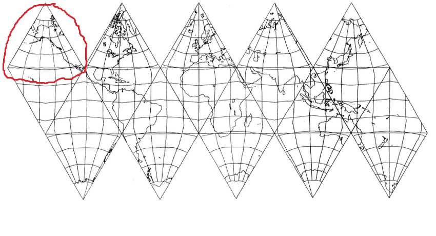
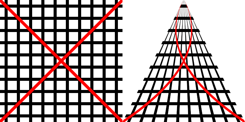
If the icosahedron is meant to be regular, then the rectangles will be squares. In this case, the triangles will be equilateral and the internal angles will all be 60°. For the top left square, what you want is to scale the lower edge by (1, 1), i.e., to leave it at its original size, the upper edge to (0, 1), i.e., it becomes a single point at the same vertical position, and the intermediate points to intermediate values for the x-value. These can be found by dividing the triangle into “bands” and finding the required width. This can be done by measuring directly or by using one of the formulae for triangle solutions (side-angle-side, etc.). Obviously, the lower limit for the height of the “bands” is 1 pixel.

The procedure is similar for the other square-triangle pairs.

If the icosahedron isn’t regular, you just have to figure out what the angles of the triangle are, which should either be known already or no problem to figure out.

So, what you need to do is to scale each band by (a, 1) for a_0, a_1 … Scaling in two dimensions by the same value in both dimensions is an affine transformation, which preserves the property of parallelity. Scaling by different values for each dimension is not an affine transformation and does not.

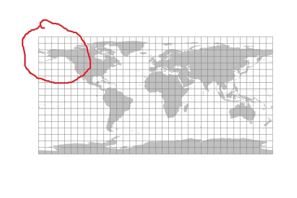
That being said, the easiest way to do this would be with vector data starting with a three-dimensional representation of a globe. The image you’re starting with is a cylindrical projection of a globe, probably the Mercator projection. The icosahedral mapping is similar to what one normally does for making globes, which is to make a “spherical development”. In this case, the globe isn’t divided into triangles but rather into “spherical biangles”. These plans for a cardboard model of a celestial sphere are an example: https://www.gnu.org/software/3dldf/graphics/clstsph3.pdf
It’s on this web page: The GNU 3DLDF Astronomy Page

These are some photos of a prototype: PaperModelers.com - View Single Post - Celestial sphere models
It would work better, i.e., appear more spherical, with more than 8 biangles (and with less stiff paper), but this model illustrates the principle.

The easiest way to make an icosahedral model would be to project the points on the sphere onto the enclosed or enclosing regular icosahedron. However, you would need a lot of points for the contours of the continents, so unless one has this data from somewhere, it would be impractical.

Incidentally, in 3D graphics programs, 4 x 4 matrices are standard for representing the affine transformations and some non-affine transformations, such as scaling by unequal values and the perspective projection. Points are represented by “homogeneous coordinates”, which have 4 values, normally called x, y and z plus an additional w-coordinate. The latter is normally 1 but is not equal to 1 (for most points) when a point is projected using the perspective projection.

I want to thank each of you for your input and suggestions. I’m in the middle of relocating to a new job site so I haven’t had the chance to try any of these things, but you’ve each given me more information and ideas than I had before.

Thanks again

You’re very welcome. When you have a chance to work on this again, please feel free to ask, if you have any questions.

Finally, I’m able to get back to work on this project.

I’ve downloaded your script and attempted to use it (thus far without success). Can you provide some guidance on it’s use? Unfortunately, there was no ‘.doc’ folder in the package when I got it.

When I ran the script, it gave me this pop-up:
image

Afterwards, it gave me this error message:
image

Based on your suggestion of using Polar Coordinate distortion, I’ve also investigated it and found this:

But want to keep pursuing both methods in order to increase the chances of finding something that will work.

Thanks

I’ve downloaded your script and attempted to use it (thus far without success). Can you provide some guidance on it’s use? Unfortunately, there was no ‘.doc’ folder in the package when I got it.

As I said, completely experimental, never meant for production.

When I ran the script, it gave me this pop-up:

OK, so far so good

Afterwards, it gave me this error message:

Could depend on the values in the popup (a Ratio value of 0 makes it crash, but differently…). Did you try it in a plain image?

A third solution is to compute a displace map (in fact if I were to rewrite this script I would make it use a displace map, that would make it run a lot faster).

This topic was automatically closed 45 days after the last reply. New replies are no longer allowed.